Welcome to our tutorial on how to build a single base single socket outlet circuit! This circuit is a common configuration in many residential and commercial buildings, and it allows you to control multiple electrical devices from a single switch. In this guide, we’ll show you how to build a circuit like this from scratch, including the tools and materials you’ll need to get started. Let’s begin.
Wiring diagram
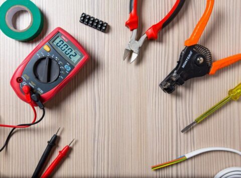
Equipment and tools: Cutting plier, combination plier, cable insulation knife, steel rule, awl, mallet, multi-meter, tester.
Items
- Single pole one-way switch 02 no’s
- Socket outlet 01 no’s
- Batten Holder 02 no’s
- Sunk Box 02 no’s
- Round Block 02
- 1/1.3 Red Wire
- 1/1.3 Blue Wire
- Bulbs 02
Procedure: First, note down on the board, according to the measurements in the layout diagram. Then, set the clips with 15cm gaps with 1 ½ clips for three wires and 1 ¾ clips for two wires. Use tintax nails to set the clips. If the wire bends, you have to set the clips 25mm away from the bend. You also have to set the clips 25mm away from the round box and sunk box. Afterwards, follow the wiring diagram and connect the wires with the help of clips once you set the sunk box using screw nails. Then, fix the round boxes in places where the bulbs should be. Set the wires for the respective sunk boxes’ switches. Then, set the holders on the round boxes and fix the bulbs. Check if the circuit is done right through a multi-meter. Here, the first bulb will be lit from the first switch and the second bulb will be lit from the second switch.
Conclusion: The circuit activated and lit the two bulbs


