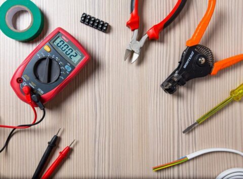
A transformer is an electromagnetic device in which two or more coils have bound together by a mutual flux. The main function of transformers is to increase or decrease the voltage and current as required. Transformers are using for power transmission and distribution as well as in-home appliances. A large power transformer has shown in Figure 1.69 (a) and a small transformer used in household appliances has shown in Figure 1.69 (b).
Design of a transformer
Figure 1.70 shows the windings of a simple transformer connected through its core. There is no electrical connection between the windings here. These windings have made of copper conductors and wrapped around limbs on either side of a laminated iron core. An insulated core uses to prevent eddy current loss.
The AC power has connected to the primary winding and the load has connected to the
secondary winding. The required voltages and currents determine the circumference of the coils and the cross-sectional area of the conductors.
The functionality of a transformer
By supplying an alternating current to the primary coil of a transformer, the magnetic flux
generated by the winding changes to Φ, which flows through the core and completes the
magnetic circuit. As the magnetic flux changes so frequently, Φ flows back through the primary
winding, the magnetic field lines have cut, causing an electromotive force, e1 opposite to the
supply voltage. This calls for self-induction. The electromotive force caused by this self-
induction can express by Faraday’s law by the following formula.
e1=-N1 dΦ 🠒 1
dt
The results of these two tests show that increasing the secondary turns of the transformer over
the primary turns can increase the secondary voltage and decrease the secondary current. These
transformers call as set-up transformers. Similarly, it appears that the secondary voltage can
reduce by reducing the secondary turns of the transformer, where the secondary current
increases. Furthermore, when the number of primary turns is equal to the secondary turns, the
primary and secondary voltages appear to be the same. Those transformers call as isolation
transformers.
Set-up Transformers
A set-up transformer is a transformer that use to increase the voltage. The following examples
illustrate the need for power transformers for power systems.
Suppose the power demand for an area where very far (100 km) from a power plant, is 5.75MW.
If the voltage is 230 V and the power factor is COS Φ = 1, then the current (I) from the supply is,
I = = = 25000 A
When such a large current flows, the potential drop (V = IR) is high and the amount of electrical power (V=I2R) is high. Therefore, the size of the cable that uses will be at least four square meters (4m2). Using these types of cables with this size is not practical at all.
To avoid this situation reduce the current by increasing the voltage and transmitting the power to the consumer. Set-up transformers use for this. That is, by transmitting the generated voltage of about 12.5 kV to a voltage of about 132 kV or 220 kV through a set-up transformer, the current decreases correspondingly, so it is possible to use a conductor with a smaller cross-sectional area.
Step-down Transformers
A step-down transformer is a transformer that uses to reduce voltage. In the case of power systems, the elevated high voltage (132 kV or 220 kV) as described above is brought to the customer’s center and then reduced to a voltage of about 33 kV by the step-down transformer, and then use for large industries. Further, differential transformers use to reduce the 33 kV voltage to 11 V and 400V, depending on the needs of each customer.
Isolating Transformers
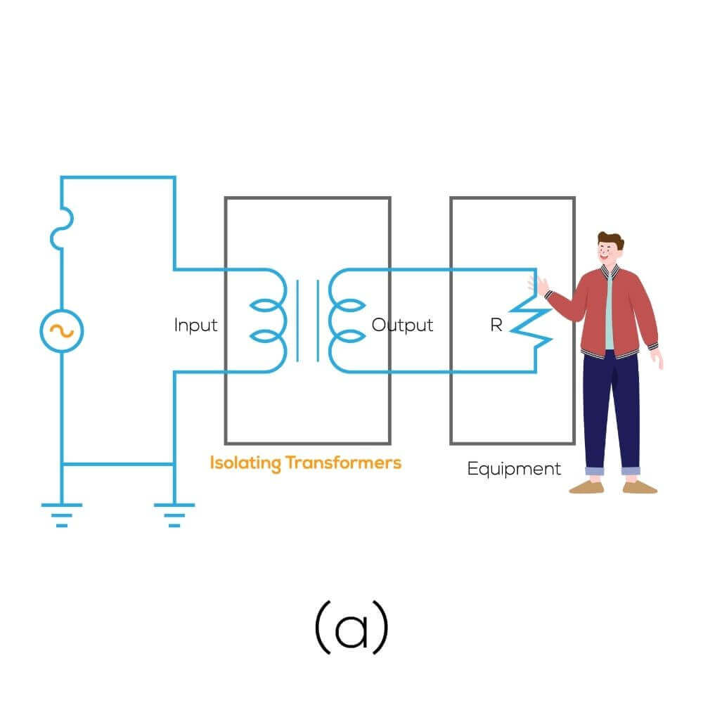
Isolating transformers are often used as a security tactic. The primary number of rounds in these transformers is equal to the number of secondary circuits. Therefore the primary and secondary voltages are the same. Since the secondary coil does not connect to the main supply, there is a ground fault in an electrical device operating at a voltage equal to the main supply voltage, but it does not connect to the main supply, so the user does not electrocute. Therefore, these use as a safety measure for soldering iron equipment in factories, sewing machines, workbenches, and bathroom appliances.
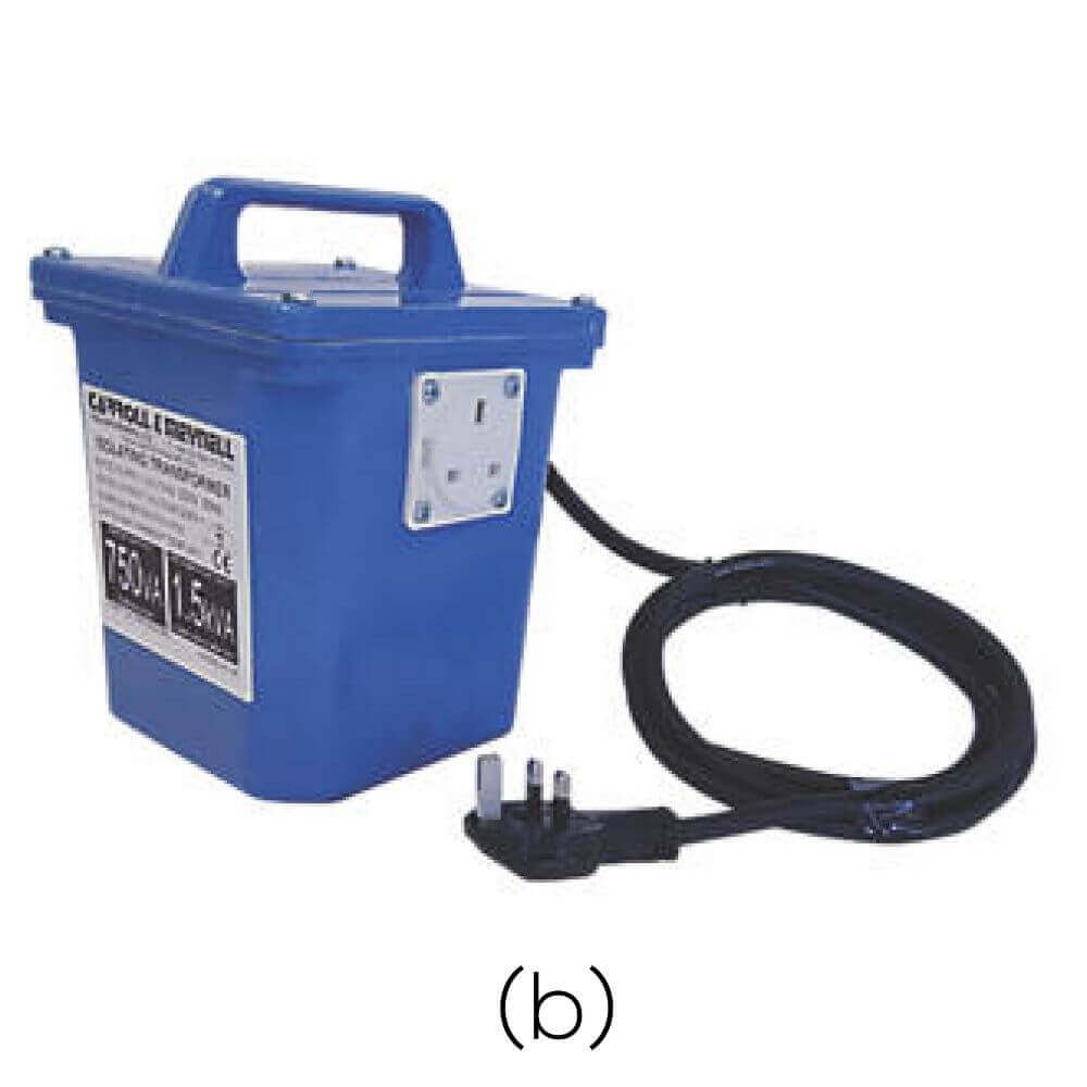
Figure 1.72 (a) shows the electrical resistance of a separator transformer due to its winding shape, and Figure 1.72 (b) shows the external appearance of an isolating transformer.
Current transformers (CT)
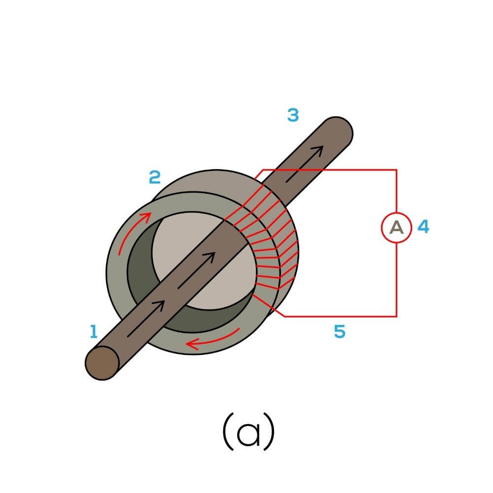
Current transformers are used to measure high currents. Figure [1.73 (a)]shows the way of measuring the current which flows through a conductor by an ammeter through a current transformer. In this case, the current generated in the coil is measured by an ammeter as the current flows through the conductor, and the surrounding magnetic flux flows through the circular core, cutting through the conductor of the current transformer. The primary coil of a current transformer is the conductor itself, and the secondary coil is the coil of the current transformer. That is because the circumference of the secondary winding is greater than the primary winding, the current in the secondary coil is very small, and the current in the secondary coil is often 5A or 1A. Namely: The current ratio of these is 50/5, 100/5,500/5, 800/5, 1000/5, etc.
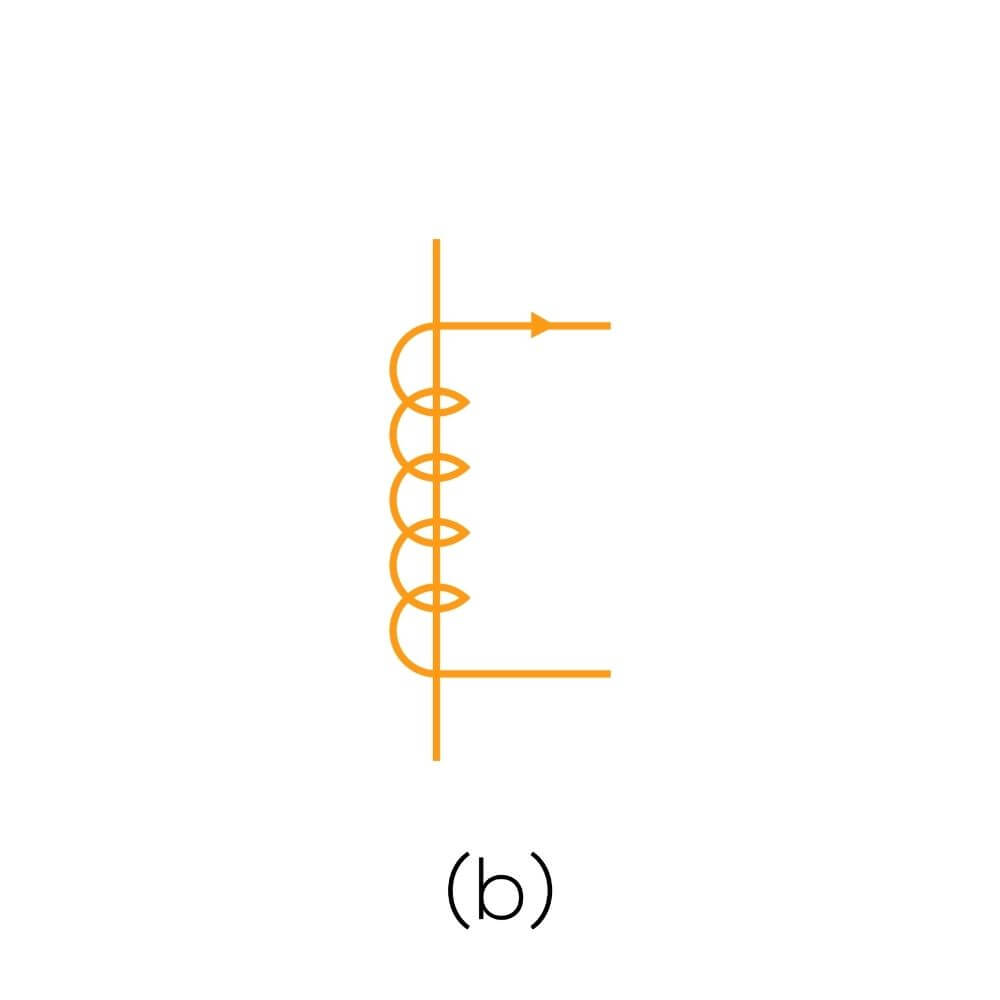
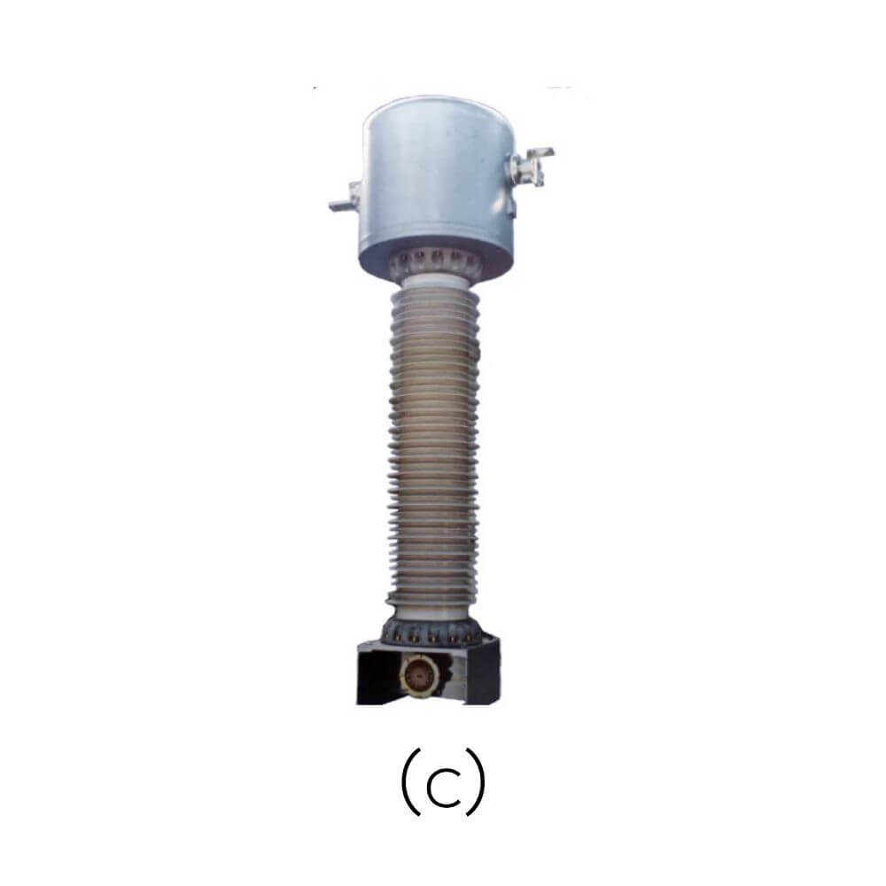
Current transformers are also used as sensors for protection measures in addition to measurements. These current transformers have a higher winding frequency of the secondary coil than the primary coil, so the terminals should never be kept open circuits as there is a high voltage at the terminals. When the ammeter does not connect, its terminals should keep as short-circuited. The code of a current transformer has given in Figure [1.73 (b)] and the external nature has shown in Figure [1.73 (c)].
Potential Transformers (PT)
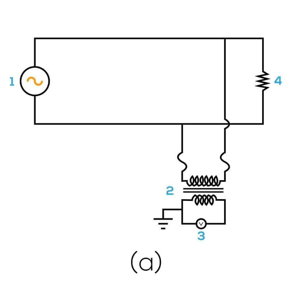
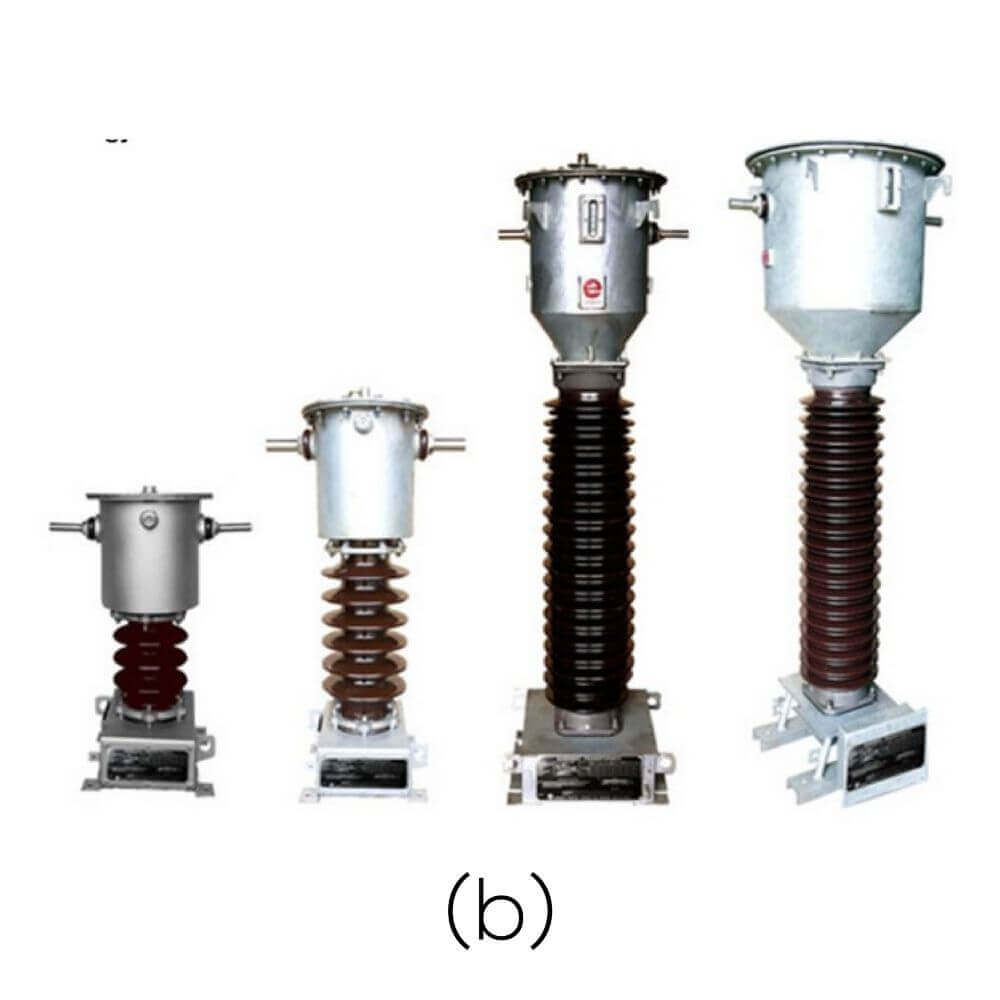
High voltages like 11kV, 33kV, 132kV, 220kV cannot measure in practice by an ordinary voltmeter. But, it connects to the voltmeter via a potential transformer as shown in Figure 1.74. Here the primary coil has more strands and the secondary coil has fewer strands. Potential transformers are also used as sensors for protective relays in addition to measurements.
Auto Transformers
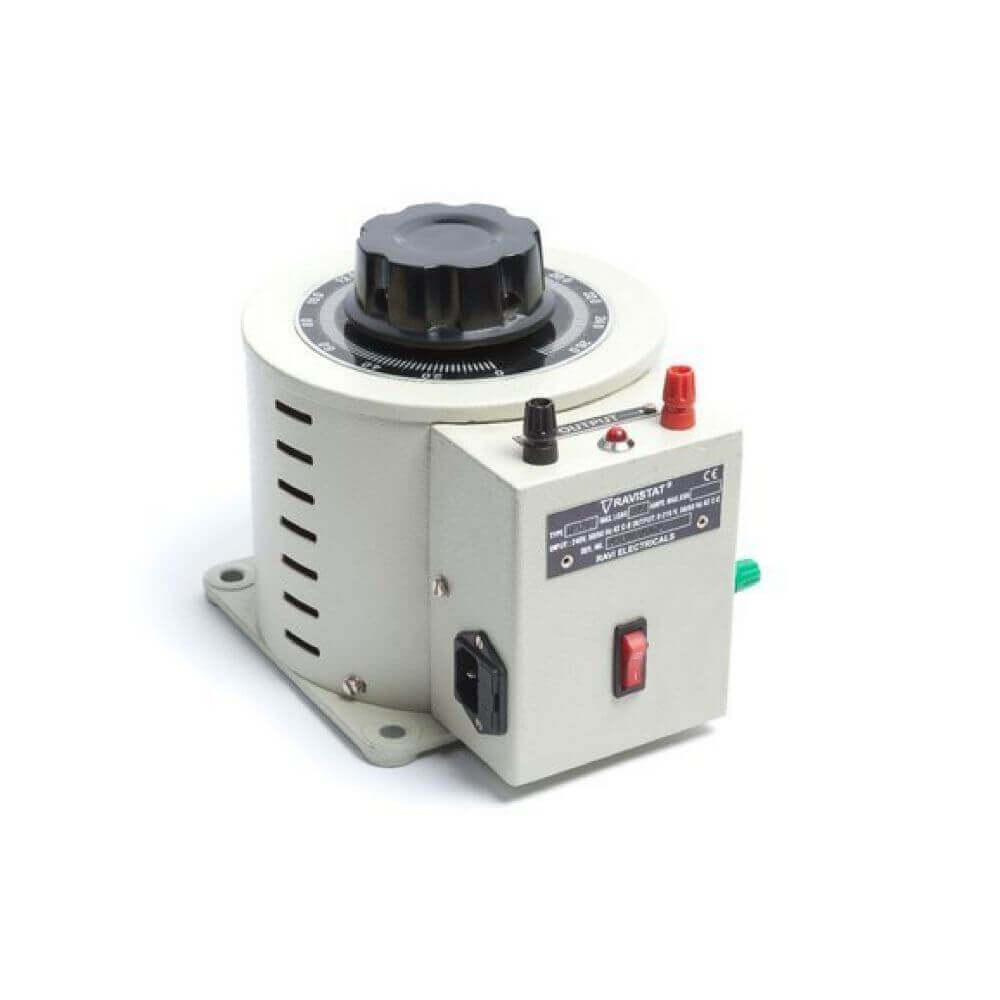
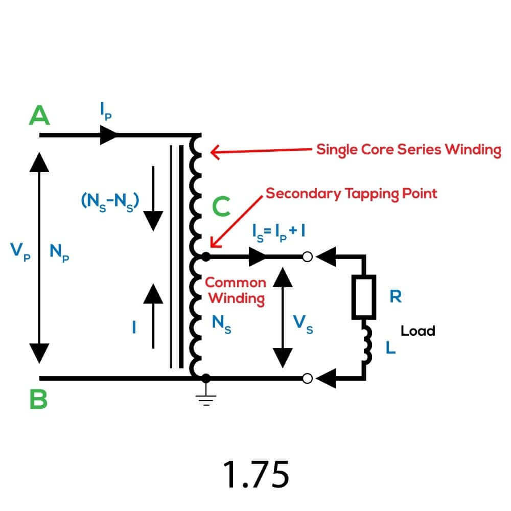
In a self-transformer, there is only one winding instead of two windings as primary and secondary. It connects as shown in Figure 1.75. It supplies Vp to the AB two terminals of the primary coil and the secondary voltage can change by adjusting the C terminal. B is the common denominator.
Self-transformer is used to increase or decrease the voltage at the indoor voltage (230V). Because two voltages are used in the transmission (for example, 132 kV and 230 kV are used in Sri Lanka), self-transformers use to connect the tunnel systems. Furthermore, automatic tap changing autotransformers use to maintain the voltage at standard values (especially in rural areas) during high power distribution.
Verities of Transformers according to the core
The transformer has been made with two primary and secondary windings, as well as a metal core that they have wrapped around. Windings consist of a copper conductor. If a metal block uses for the core, So the core will overheat due to the energy loss caused by the eddy currents that surround the magnetic field lines as the magnetic flux flows through it. This reduces the efficiency of the transformer. Therefore the core has made of metal sheets with sheets insulated from each other.
So there are two types of transformers depending on the nature of the magnetic core.
- Core type
- Shell type
Figure 1.76 shows an outline of these transformers. Leaking magnetic flux can be minimized by using a shell-type transformer.
Check out our articles about Alternating Current Motors and Control circuits for forward and reverse motors. You can read more about Transformers in Wikipedia.