Control circuits for forward and reverse motors are used in a variety of applications to control the direction of a motor. These circuits can be used in conveyor systems, cranes, and many other types of machinery to change the direction of motion. In this blog post, we will discuss the basics of a control circuit for a forward and reverse motor, including the components that make up the circuit and how they work together to change the direction of the motor. Whether you are a beginner or an experienced engineer, this post will provide you with a solid understanding of how control circuits for forward and reverse motors work.
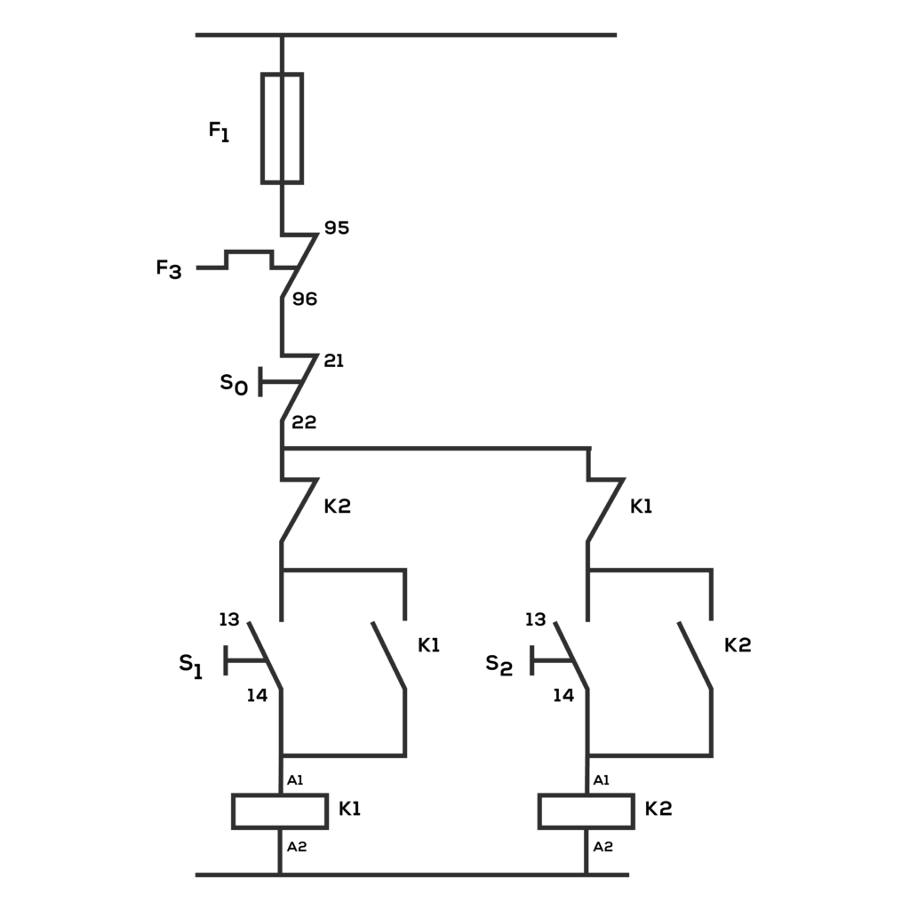
Layout diagram
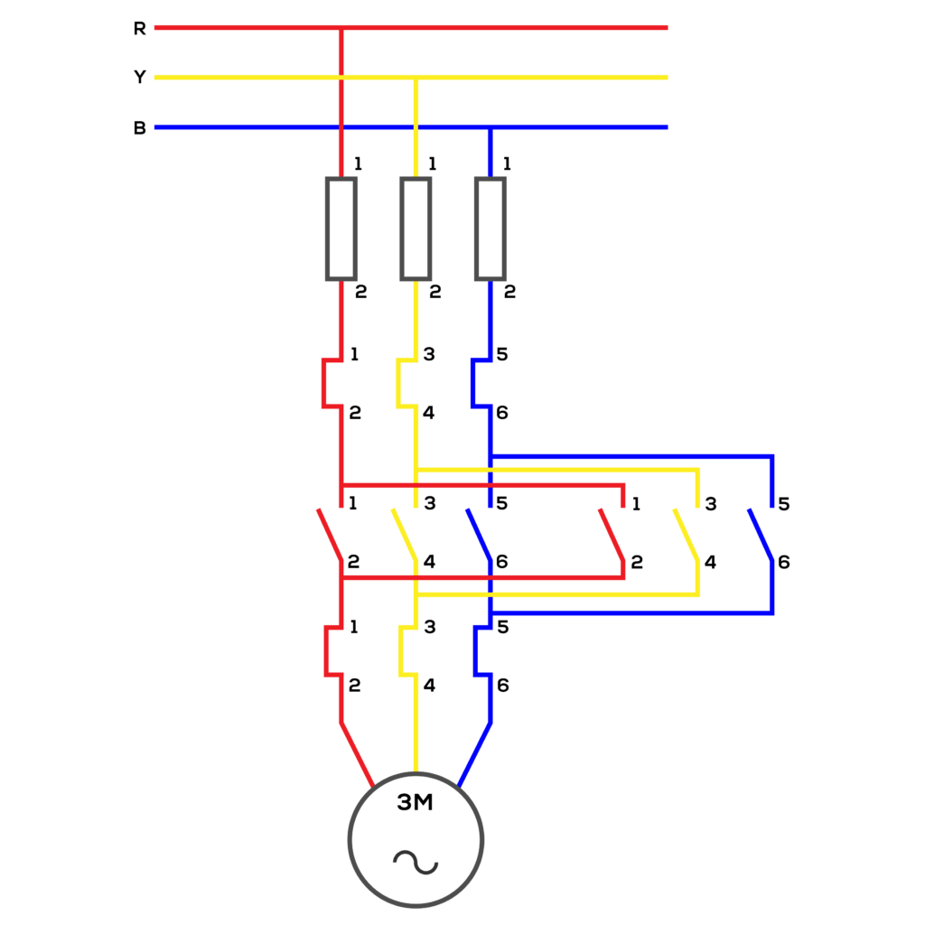
Wiring diagram
Items:
- Contactor Switch-02
- Push Button (NC, NO) -03
- Overload -1
Procedure: First, create the control circuit for forward and reverse motor. Then, create its power circuit accordingly. Then, set all the items for the power circuit. Then, check the power circuit with a multi-meter and give power supply of 230V. Then, check the third power circuit and fix the motor to it. Then connect it to the main power supply.
Activity: When S1 activates, the K1 contactor starts and pushes the motor forward. When S2 activates, the K2 contactor starts and reverse the motor. When S0 switches on, the motor stops.
Conclusion: Circuit activated correctly