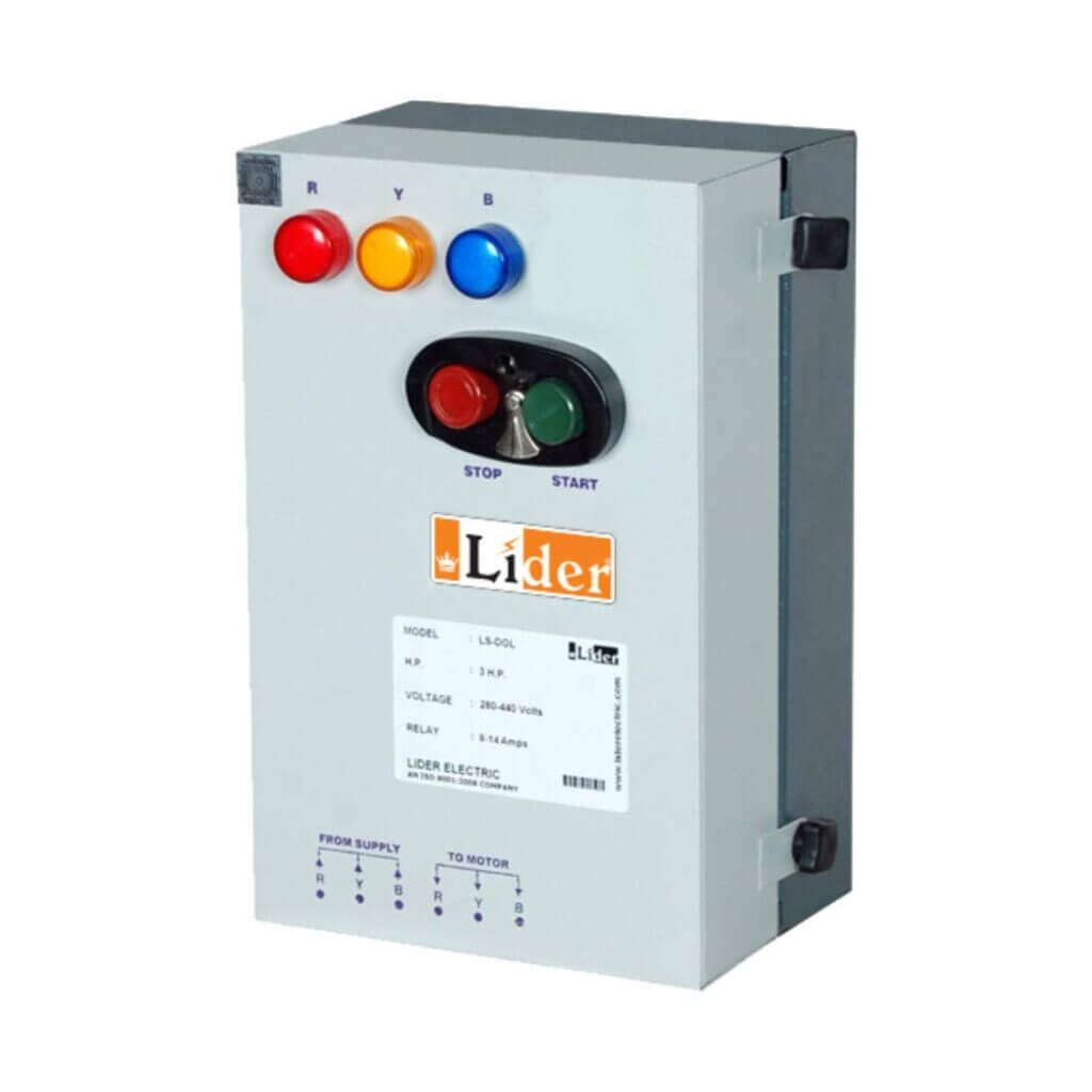
Welcome to our blog post on DOL with indicator! In this post, we’ll be taking a closer look at direct online starters with indicator lamps, and how they work in electrical systems. We’ll cover the different components that make up a DOL with indicator circuit, including contactor switches, push buttons, overloads, and indicator lamps. We’ll also provide a step-by-step guide on how to set up and test a DOL with indicator circuit, including how to properly draw the control and power circuits and how to safely connect everything to the main power supply. Whether you’re an electrician looking to add a DOL with indicator to your toolkit, or a beginner looking to learn more about electrical systems, this post will provide all the information you need.

Layout diagram

Wiring diagram
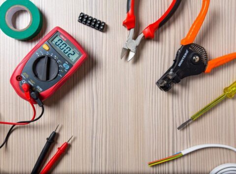
Items:
- Contactor Switch-01
- Push Button (NC, NO) -02
- Overload -1
- Indicator lamp -1
Procedure: First, draw the control circuit. The, draw the power circuit accordingly. Draw the wires and fix the items for the power circuit. Then, check the circuit with a multi-meter and give power supply of 230V and check the circuit’s state. Then fix the items in the power circuit and test it with a multi-meter. Afterward, set the motor to the power circuit. Then, connect these circuits to the main power supply.
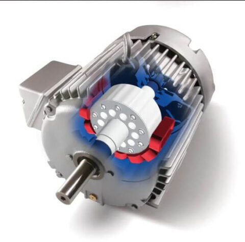
Activity: When S1 activates, K1 contactor activates and starts the motor. Then the DOL indicator lamp also lights up. You can switch off the motor and the indicator lamp from S0.
Conclusion: Circuit activated correctly