A star delta auto control circuit is a type of electrical circuit used to control the starting and stopping of three-phase motors. This circuit is designed to automatically switch the motor’s connection from a “delta” configuration to a “star” configuration during the starting and stopping process, which allows the motor to start and stop smoothly without any sudden surges in current. In this post, we will take a closer look at how a star delta auto control circuit works, including the components that make up the circuit and the sequence of events that occurs during the starting and stopping process. By the end of this post, you will have a solid understanding of how a star delta auto control circuit operates.
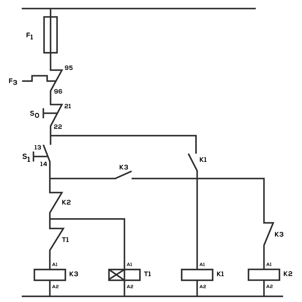
Layout diagram
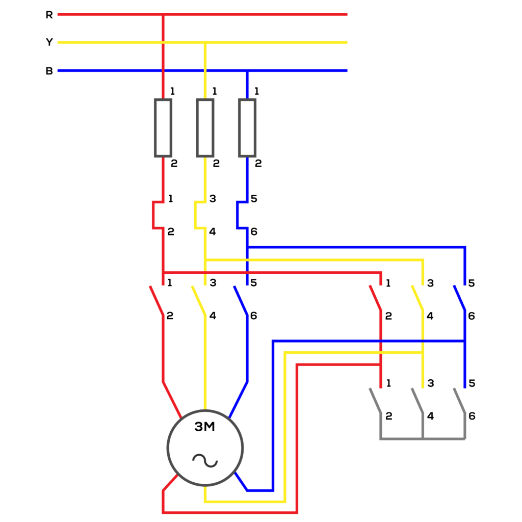
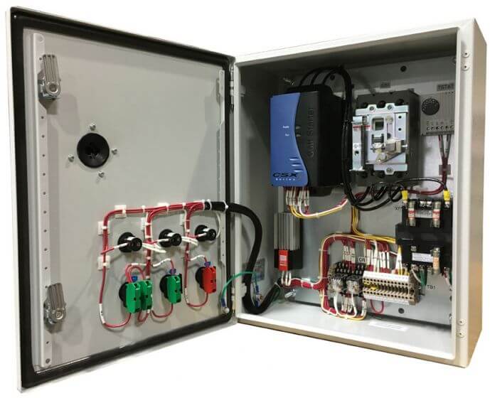
Wiring diagram
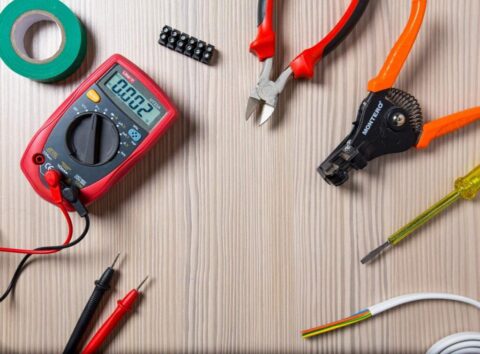
Items:
- Contractor Switch – 3
- Overload – 1
- Push button – 2
- Timer – 1
Procedure: First, draw the circuit for the star delta auto control circuit. Then make the power circuit for that accordingly. Add all the items and equipment on the circuit board. Then, check the power circuit with a multi-meter and give 230V power supply. Then, set the motor to the third power circuit. Then connect it to the main power supply.
Activity: When S1 activates, K3 and K1 contactors start and switch on the motor in the star mode. Then, when the timer stops, K3 contactor stops, K2 and K1 contactors start and switch on the motor in the delta mode.
Conclusion: Circuit activated correctly